Can we accurately screen MOFs for carbon capture applications using high throughput computational screening workflows?
To reach “net zero”, humanity must act now to reduce the levels of CO2 in the atmosphere. Carbon capture and sequestration (CCS) technologies are needed to achieve this, but the challenge lies in the additional energy and financial costs associated with the process. Chemical absorption using amine solvents are the currently preferred technologies for (post-combustion) carbon capture, however adsorption using solid adsorbents have emerged as an energy-efficient alternative to absorption processes due to their low regeneration energy, high CO2 selectivity, and high CO2 capture capacity.
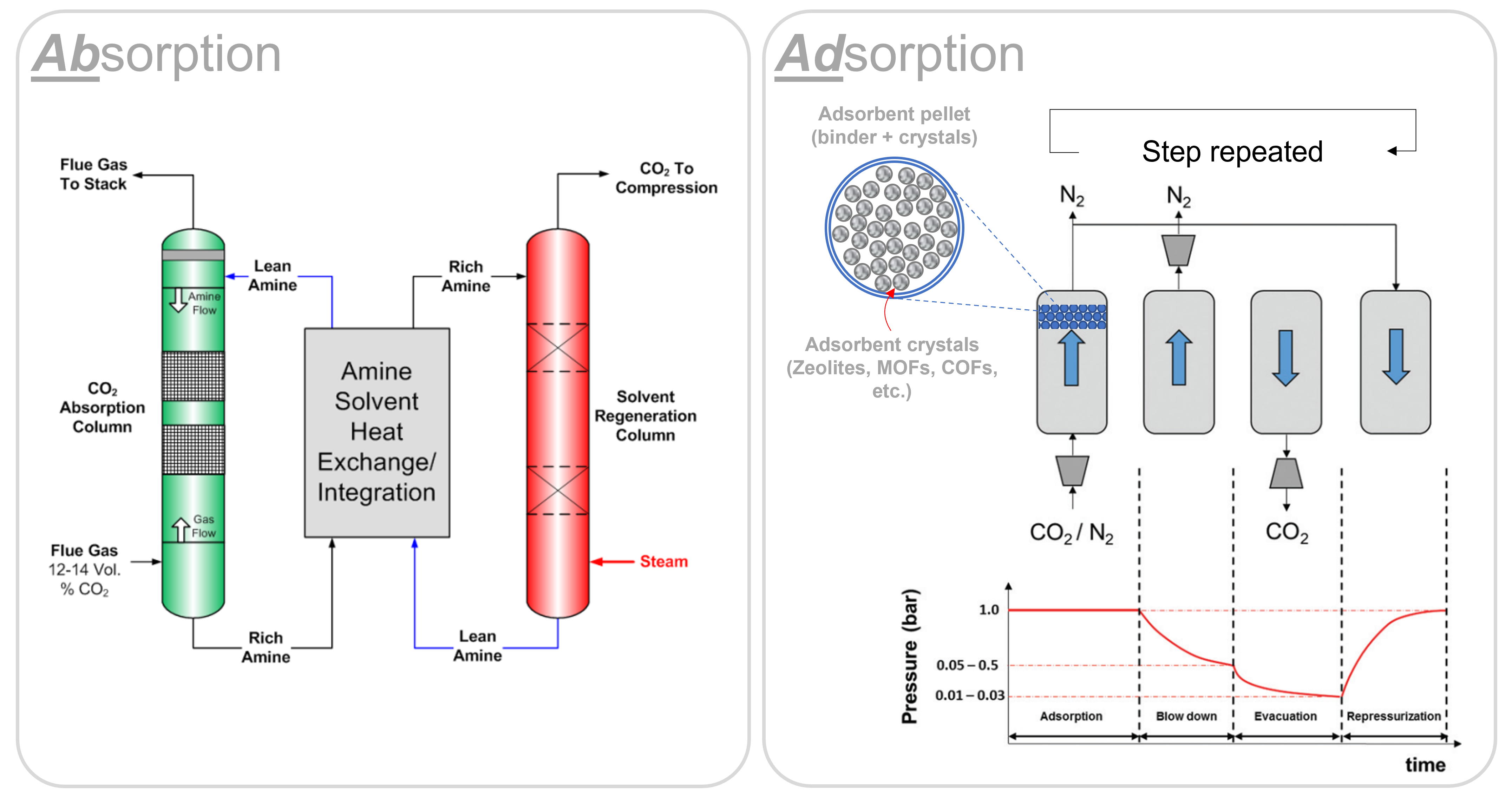
One of the major advantages of adsorption technologies is routed in its cyclic nature: one can configure a variety of ‘cycles’ with different sequences and steps to achieve the best separation performance for a given CO2 capture source. Pressure swing adsorption (PSA), for example, works by cycling the pressure of a gas mixture between high and low pressures. The adsorbent selectively captures CO2 molecules when the pressure is high and releases them when the pressure is low. This cycle is repeated multiple times, allowing the adsorbent to capture a significant amount of CO2 from industrial flue gases, or even from the atmosphere!
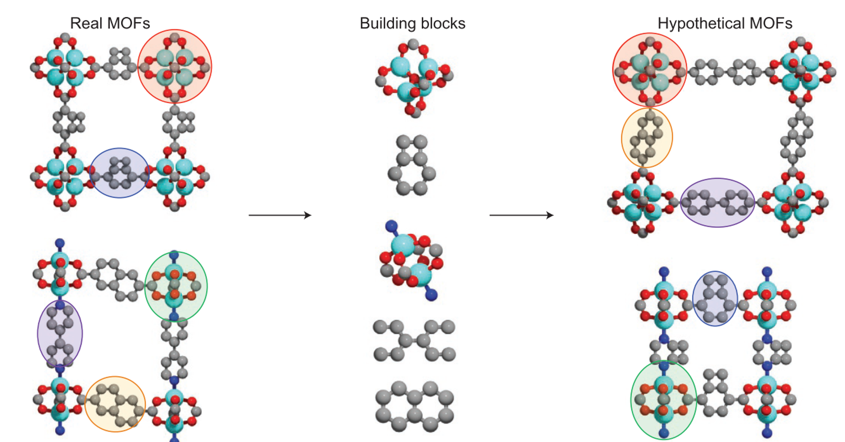
At the heart of the adsorption process is the material used as an adsorbent. The efficiency of the process critically depends on the characteristics of this material (among other things). So, an important question to ask is: for a given CO2 emission sector, can we find the best adsorbent? Amongst the pool of porous materials that exist, this endeavour is akin to finding a needle in a haystack. Yet, the demand for CCS has prompted many research groups to pose, and attempt to answer, this exact question. Quite often the focus of these studies is the subclass of porous materials known as MOFs, a.k.a., metal organic frameworks. These materials are constructed from organic linkers and inorganic metal node complexes in a lego-like fashion (Fig.2).
Currently, over 100,000 experimentally synthesised MOFs have been reported in the Cambridge Structural Database. But, by virtue of their modular nature, the number of possible MOF structures, chemistries, and therefore properties, are virtually infinite. Obviously, testing each of these materials using traditional trial-and-error experimentation is too costly and time consuming to be practical, and so we rely on computational tools to sift through these structures and identify the most promising MOFs for various applications.
These computational screening workflows typically depend on the use of molecular simulation to obtain thermodynamic and kinetic properties of systems that may be hard or even impossible to measure through experiment. The data obtained using these simulation techniques can be used to rank MOFs by their ability to selectively adsorb CO2 over N2, for example. However, concurrent developments in both molecular simulations and advanced process simulations have led to carbon capture community to the following proposition: what if the screening of porous materials for dynamic adsorption processes can be implemented using realistic process simulations while the microscale properties of materials are provided by molecular simulations? This multiscale screening protocol provides a more realistic approach to material selection (Fig.3).
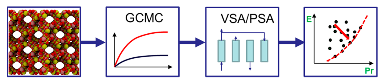
Okay, let’s break this approach down. Starting with a MOF crystal structure, we use a simulation technique called Grand Canonical Monte Carlo (GCMC) to see how well a material can adsorb CO2 over other gaseous components in a gas mixture. In other words, we compute the adsorption equilibrium (or isotherm) between the MOF and all gaseous species. Then, we use this data to create a model of how the material would work in a real-world CO2 capture process. We adjust different variables of the PSA cycle, like pressure and cycle duration, to find the best combination of process parameters for the material. We are trying to balance different objectives during this adjustment, like achieving high productivity (moles of CO2 captured per kg of adsorbent per second) while using the least amount of energy (kWh per tonne of CO2 captured). These objectives are in competition with one another: in order to achieve high productivity, we have to use more energy. We therefore represent the energy-productivity trade-off using a Pareto front (Fig.3 on the right). This curve defines the best possible performance of a material in a given PSA process. Points to the top left of this curve are sub-optimal process configurations, and points to the bottom right of this curve are impossible to achieve. We can then compare the Pareto fronts for two different materials to see which one works best.
This is a fairly clean representation of a multiscale screening workflow. However, many design choices took place behind the scenes. One of them was choosing how to generate the adsorption data using molecular simulations, which is a crucial first step in the simulation pipeline. But how do we even simulate adsorption in MOFs, and why is it so important for computational screening?
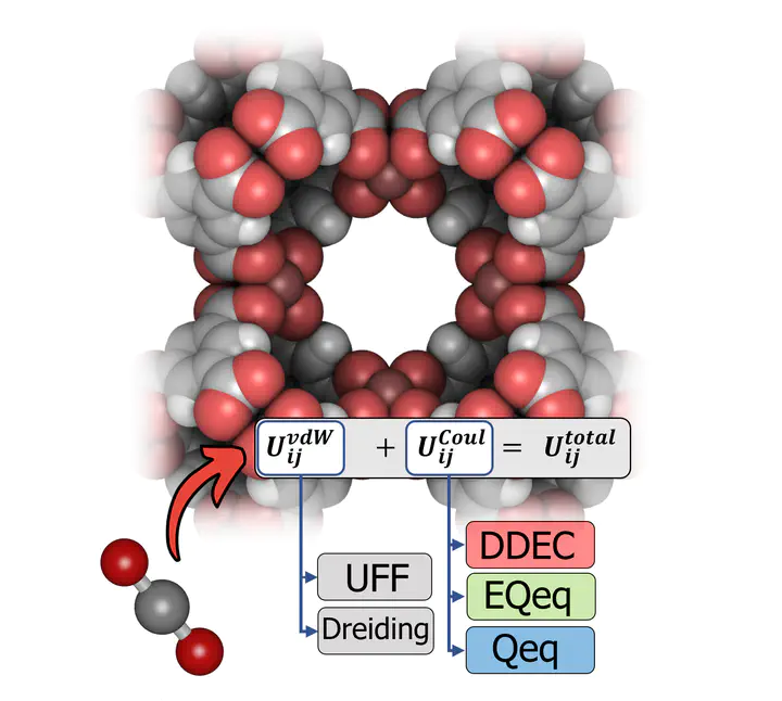
Well, to predict how MOFs capture CO2, the interactions between the MOF and CO2 must be accurately described. This is done through a set of equations and molecular parameters called a forcefield. In particular, we (as a minimum) must be able to describe the short-range dispersion / repulsion interactions and the long-range electrostatic interactions. A Lennard-Jones potential (which requires two molecular parameters per element) and a Coulomb potential (which can be resolved by calculating partial charges for each atom in the simulation system) can be used to simulate the short-range and long-range interactions, respectively. Therefore, our forcefield is defined as a combination of parameters for the Lennard-Jones (LJ) potential and a protocol to calculate the partial charges. Common choices include the UFF or Dreiding LJ parameter sets, in combination with partial charges assigned by either quantum mechanical calculations (such as the DDEC method) or by charge equilibration schemes (such as the Qeq and EQeq methods).The choices made at the molecular level will influence the process-level predictions, and therefore the final recommendations which emerge from multiscale computational screening studies.
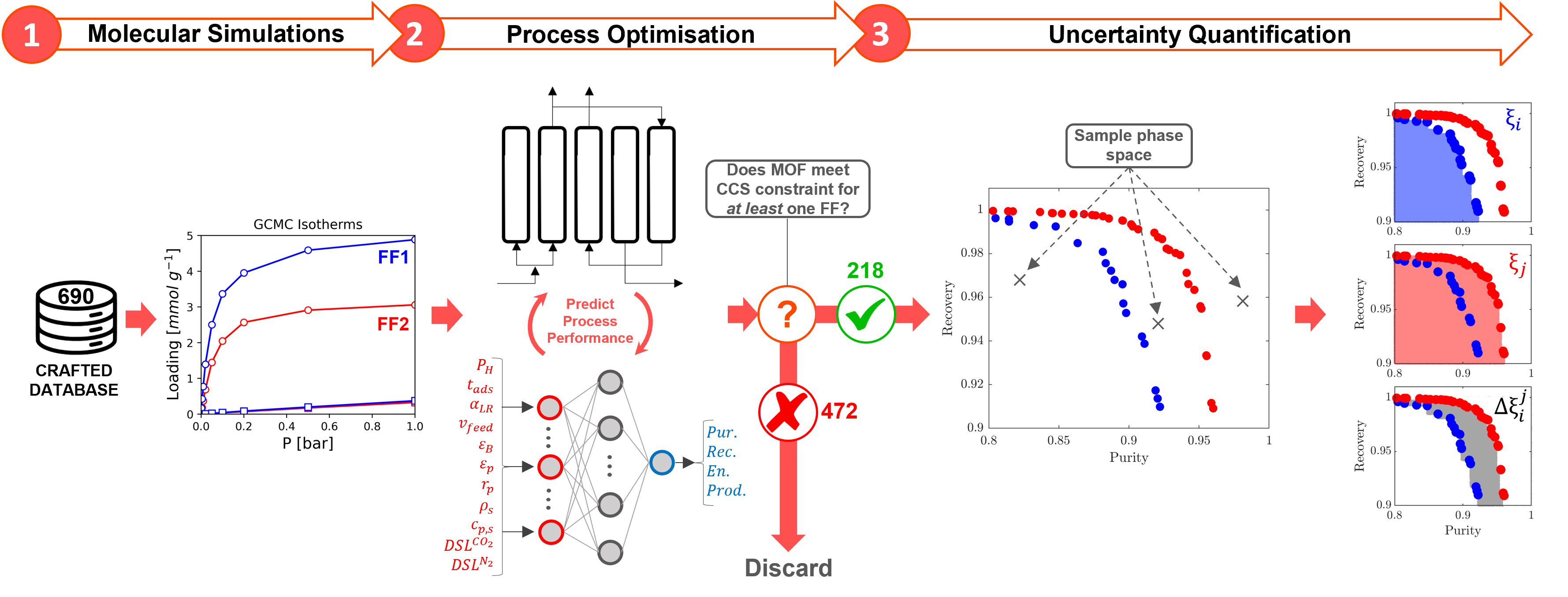
In light of these considerations, we asked in a recent study: can we trust the material rankings from high throughput screening of porous materials for carbon capture based on off-the shelf molecular forcefields? To explore these issues, we computationally screened the performance of 690 MOFs using a multiscale workflow with integrated uncertainty quantification (Fig.4). We generated distributions of CO2 and N2 adsorption behaviours in each of these MOFs by performing molecular simulations using different combinations of the LJ parameter sets and partial charge assignment methods. Using this data, we evaluated how the performance of materials, and therefore the final rankings obtained using process simulation, changes using different forcefields. Through our analysis, we find that:
- The computational ranking of materials appears to depend on the choice of the molecular FF to a significant extent.
- From the pool of molecular modelling choices we consider, the choice of charge assignment scheme represents the largest source of uncertainty at the process-level.
- Partial charges assigned by charge equilibration methods such as Qeq and EQeq are unable to reproduce the adsorption behaviours of charges derived from quantum mechanical (QM) calculations such as DDEC with sufficient accuracy to guarantee consistent process-level rankings. As such, we recommend avoiding using charge equilibration methods when the electrostatic interactions are important for adsorption, such as CO2 adsorption in MOFs.
- When QM charges are not available and are computationally unfeasible to obtain, we confirmed in our investigation that QM charges can be replaced by machine learning models which are trained to predict charges derived from QM calculations. These ML models are attractive alternative to the Qeq and EQeq schemes that can effectively minimise the uncertainties originating from partial charge assignment.
- We still lack a consistent, experimentally validated set of molecular parameters to describe the LJ interactions in MOFs. Until this issue is addressed, one has to accept the considerable uncertainties embedded within process-level predictions which make use of adsorption data generated using generic LJ FFs.
Conor Cleeton
Ph.D. student
My work involves the modelling of energy efficient adsorption and carbon capture processes at multiple scales, from the molecular level to the industrial process level.